Vision Simulation System
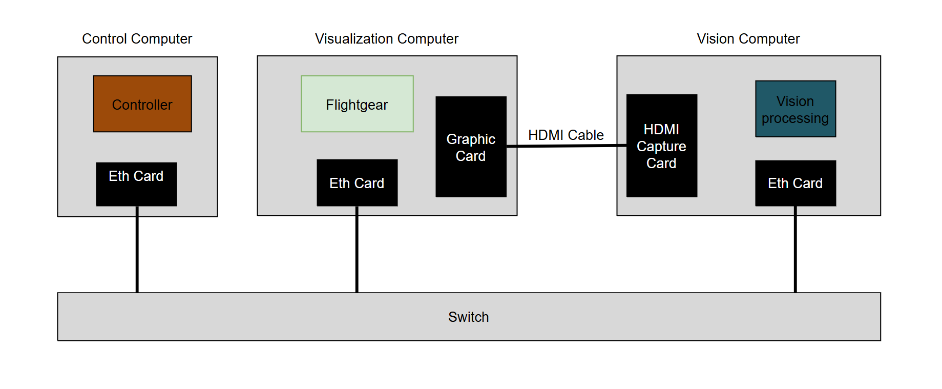
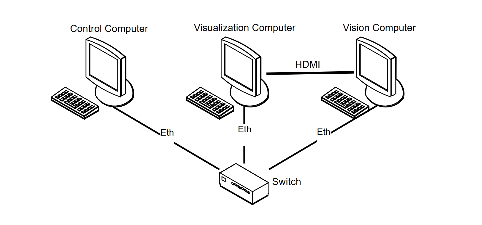
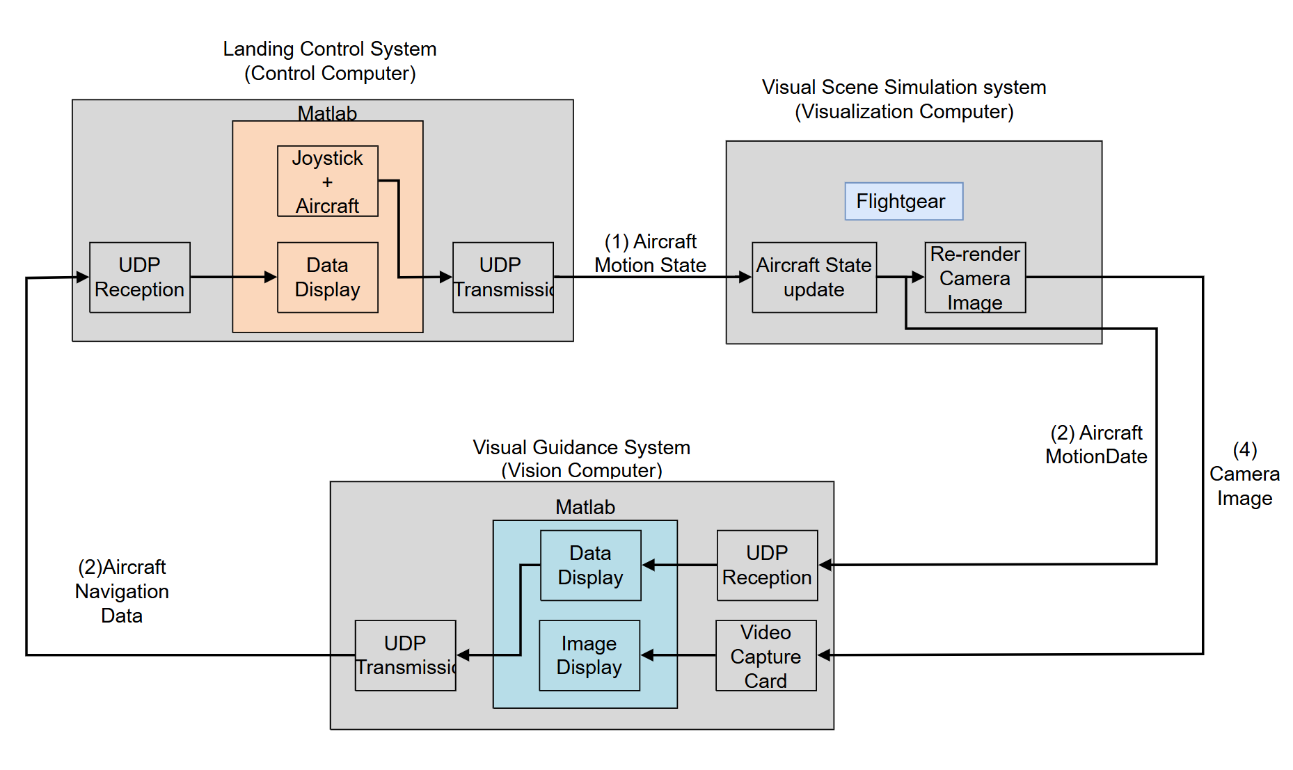
This was my Master's thesis project(2014). The system consists of three interconnected computers, each playing a specific role:
-
The control computer is responsible for controlling. It outputs real-time position and attitude data to the visual system.
-
The visual unit, using
FlightGear, updates the aircraft’s state based on this data and refreshes the virtual camera's view. It then outputs the camera image data to the vision processing unit. -
The vision unit captures the image signals for analysis and computation, then outputs the aircraft's navigation position data to the control computer.
-
The process loops back to step (1), forming a closed-loop system.
How the visulization works
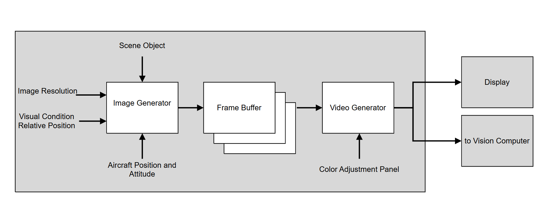
This is the key part, this project utilizes and configs FlightGear to genearate the view of the camera onboard the aircraft.
The image generator works in the digital but the same way as the optical camera.
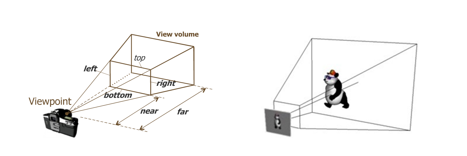
The best part of this simulation system is that you can build whatever object and let the camera to look at it. Here I make a giant cheeseboard and let the aircraft look at it from different position.
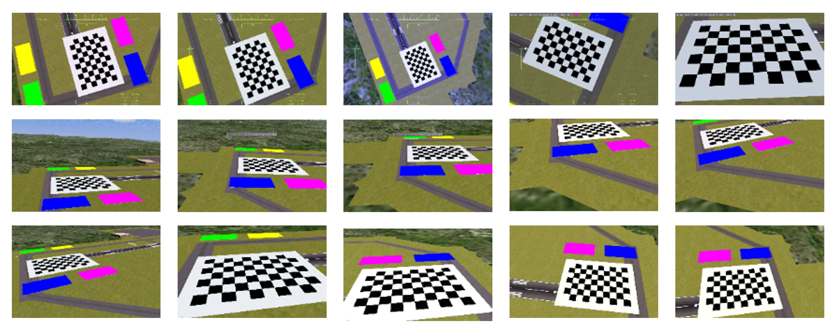
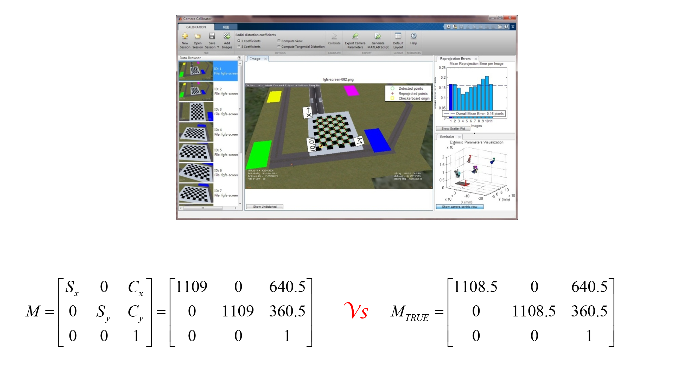
And calibrate it to confirm the outcome is the same as the configuration expectes.
How the closeloop system works
The closeloop diagram
I made a Labview program for the vision processing.
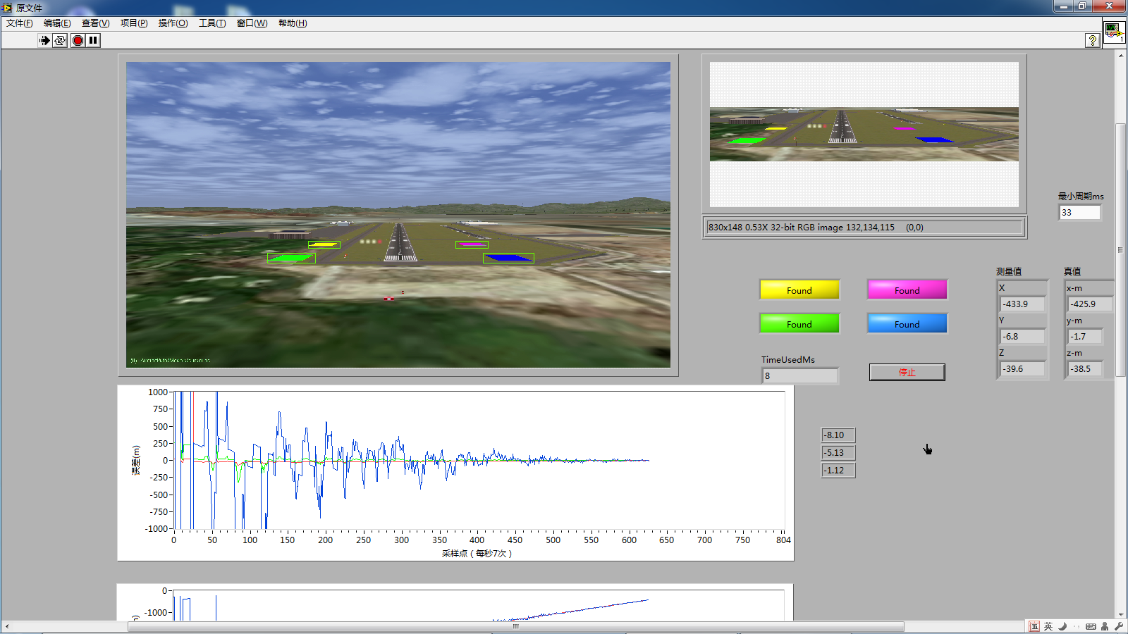
The closeloop testing:
Closeloop testing
Reference
[A Simulation System for Vision-Based Autonomous Landing of Unmanned Aerial Vehicles]